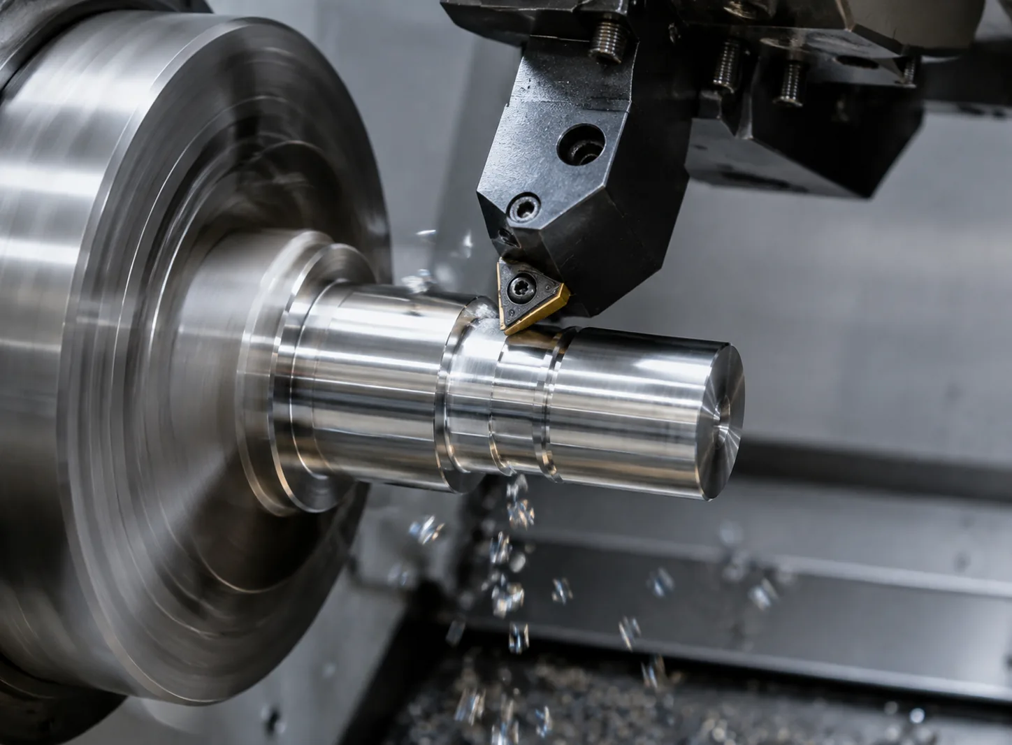
Design for Manufacture: Five Drawing Choices That Decide Whether Your Part Machines Cleanly
A manufacturing engineer's DFM checklist: internal corner radii, thin walls, deep holes, standard threads, and tolerance stacking — and how each
The drawing choices that decide whether a part machines cleanly or fights the process — corners, walls, holes, threads, tolerances and material.
Most expensive parts are not expensive because of the material. They are expensive because the drawing fights the process — and by the time the part reaches a machine, the cost is already locked in. A DFM review before cutting catches those choices without changing the part's function.
We run a DFM check on every quote, free. It is not a gate to upsell you — it is a list of the specific changes that will make your part cheaper, faster, or both. You decide which to accept.

A mill cuts with a round tool, so a truly sharp internal corner needs a small relief or a different process. Opening an internal radius from R1 to R3 can save 30–40% of cycle time on a pocket — give the corner a radius near your smallest practical cutter.
Walls under about 0.5 mm in aluminium, or 1 mm in steel, chatter and deflect unless the whole strategy is built around them. If the wall only needs to be thin locally, keep the rest of the web thick and relieve just the feature.
Keep drill depth under about 4× the diameter for a standard drill. Beyond that the drill wanders, coolant stops reaching the tip, and the hole walks off position. Deeper than 10× needs gun drilling or a specialist process — and a different price.
A tapped hole needs clearance for the tap's lead. Leave a relief or undercut at the bottom of a blind tapped hole, or specify thread milling for a thread that must run close to the bottom.
Every decimal place adds setups, inspection and scrap. Tolerance only the features that drive function; give everything else a general tolerance and the part costs what it should.
| Feature | Good practice | Why |
|---|---|---|
| Internal radius | ≥ 1/3 cutter diameter | Avoids tool chatter and extra passes |
| Wall thickness | ≥ 0.5 mm (Al), ≥ 1 mm (steel) | Prevents deflection and distortion |
| Hole depth | ≤ 4× diameter | Straight, on-position holes |
| Minimum hole | ≥ Ø0.3 mm (milling) | Below this needs micro tooling |
| Thread relief | ≥ 1.5× pitch | Room for the tap lead |
| Corner on 5-axis | radius ≥ tool radius | Single-setup compound angles |
This is the short version. Send us your STEP file and the DFM notes come back with the quote — use the quote form or see our rapid prototyping service to test a design quickly.

A manufacturing engineer's DFM checklist: internal corner radii, thin walls, deep holes, standard threads, and tolerance stacking — and how each

The realities of micro-milling and micro-turning for miniature and electronics parts — tool deflection, spindle speed, and why rigidity beats raw power
Send your drawings and requirements. Quote, lead time and DFM feedback by email.