
Finishing
Surface Finish Ra: What the Number Means and How Machining Controls It
Why Ra alone does not describe a surface, how cutter path, stepover, and nose radius drive finish, and where a surface grinder is the only right tool.
A practical guide to what tolerance you should put on the drawing, and what each process can actually hold — general tolerances, per-process achievable tolerances, and surface finish.
If a dimension has no tolerance, ISO 2768-1 supplies a default. Most drawings we see use the medium class; fine class is for features that genuinely matter. Here is what each class means for a linear dimension.
| Nominal size (mm) | Fine (f) | Medium (m) | Coarse (c) |
|---|---|---|---|
| 0.5 – 3 | ±0.05 | ±0.1 | ±0.2 |
| 3 – 6 | ±0.05 | ±0.1 | ±0.3 |
| 6 – 30 | ±0.1 | ±0.2 | ±0.5 |
| 30 – 120 | ±0.15 | ±0.3 | ±0.8 |
| 120 – 400 | ±0.2 | ±0.5 | ±1.2 |
| 400 – 1000 | ±0.3 | ±0.8 | ±2.0 |
These are the tolerances we hold in normal production, not best-case lab demos. They assume a sensible drawing and a competent setup; a tolerance tighter than the "production" column costs extra in setup, inspection and scrap.
| Process | Typical achievable | Notes |
|---|---|---|
| CNC milling (3/4-axis) | ±0.05 mm typical | Holes, pockets, faces, plates |
| CNC turning | ±0.05 mm typical | Bores and ODs, one-setup concentricity |
| Swiss / sliding-head | ±0.05 mm typical | Long slender parts, sub-spindle work |
| 5-axis machining | ±0.05 mm typical | Compound angles, one setup |
| Turn-mill | ±0.05 mm typical | Turned + milled in one clamping |
Surface finish is specified as Ra in micrometres. Lower is not always better — a sealing face needs a specific Ra band, not just "the smoothest you can make".
| Process | Typical Ra (µm) | Notes |
|---|---|---|
| Milling (finishing pass) | 0.8 – 1.6 | Ball nose with fine stepover |
| Turning | 0.4 – 0.8 | Finish pass with correct nose radius |
| Swiss turning | 0.4 – 0.8 | High-pressure coolant |
| As-milled (rough) | 3.2 – 6.3 | Default when no finish is called out |
Geometric tolerances behave differently from size tolerances. These are the values we routinely hold on a production part; tighter is possible on individual features with the right setup.
| Characteristic | Routinely held | What it costs to tighten |
|---|---|---|
| Flatness | Drawing-driven | More finishing passes, lighter cuts |
| Parallelism | Drawing-driven | Square setups, datum discipline |
| Perpendicularity | Drawing-driven | Location vs datums |
| Position (true position) | Confirmed by optical measuring | Probe / 2D inspection |
| Concentricity / runout | Single-setup turning | One-setup turning or turn-mill |
Tolerance is only half the story — proving the process holds it is the other. See how we verify with quality assurance and what our machining capabilities actually cover.
Why Ra alone does not describe a surface, how cutter path, stepover, and nose radius drive finish, and where a surface grinder is the only right tool.

How GD&T symbols on a print decide whether a CNC part is manufacturable and affordable. True position, profile, datums, and the tolerance traps to avoid.
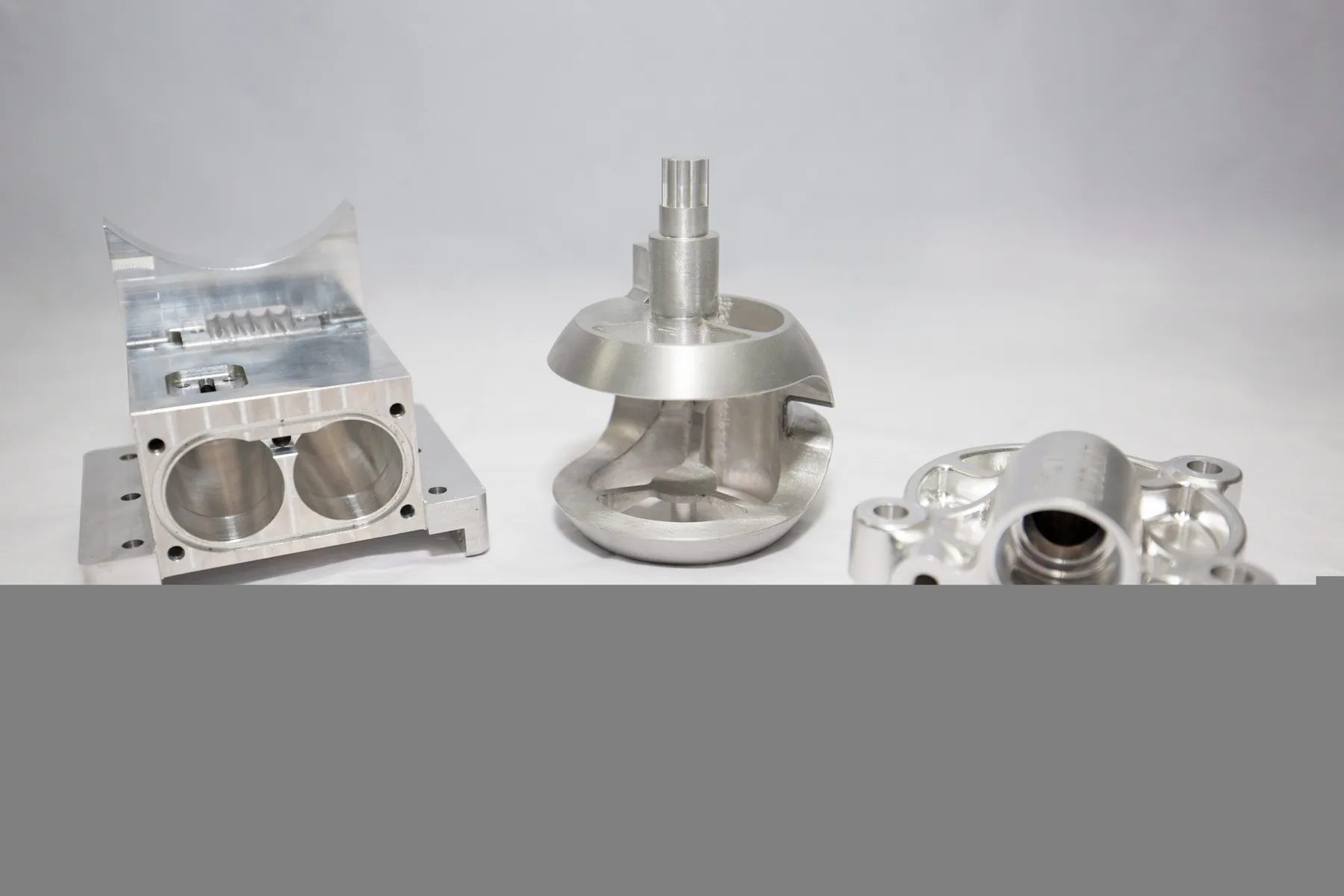
Precision boring holds roundness, straightness, and position in deep holes. How boring bar deflection, tool selection, and in-process checks decide the result.
Send your drawings and requirements. Quote, lead time and DFM feedback by email.