End-of-arm tooling — the gripper, fingers, and mounting plate bolted to the wrist of a robot — is the part of an automation cell that actually touches the product, and it is also the part most likely to wear out, drift, or collide with something. Unlike a fixture that sits still on a table, an EOAT gets accelerated and decelerated hundreds of times an hour, so every gram of its mass costs the robot cycle time and every tolerance it loses shows up as a dropped part or a misaligned pick. Machining EOAT well means trading off three things at once: keeping the assembly light, holding the gripping geometry accurate, and making the contact surfaces tough enough to survive the duty. This guide walks through how to design and machine each of those so the end effector holds the part the same way on the ten-thousandth cycle as on the first.
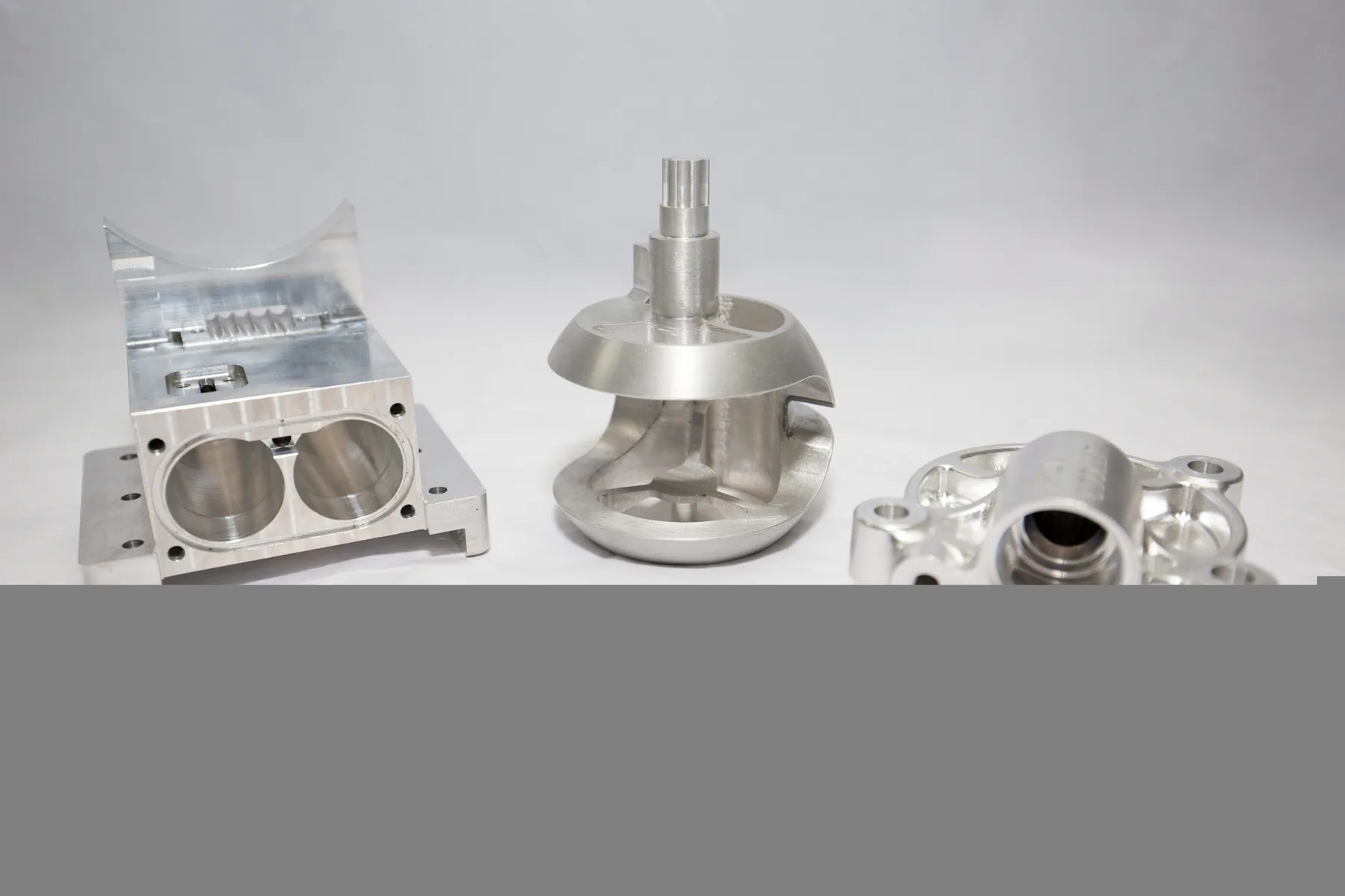
Mass is the real spec: lighten the tooling before you strengthen it
The first number an automation engineer cares about on an EOAT is not its strength but its weight, because every kilogram bolted to the wrist is a kilogram the arm has to start and stop, and the starting and stopping is what eats the cycle budget. A heavier end effector needs a larger robot for the same payload, or a slower move profile for the same robot, and both of those cost more than the material you save by leaving the part heavy. The payoff is compounding: a lighter gripper accelerates faster, so the arm reaches the part sooner, so the cell produces more parts per hour, so the whole line needs fewer robots. That is why EOAT design starts from the load, not from the drawing.
The practical move is to put material only where the load actually flows. A gripper finger has a stiff spine that carries the grip force from the actuator to the fingertips, and everything around that spine is fair game for a pocket, a lightening hole, or a thin web. Milling pockets into a finger instead of leaving it a solid block is not cosmetic — it is the difference between a tool the arm can fling around at full speed and one it has to baby. The same rule applies to the mounting plate: it does not need to be a uniform slab, it needs to be stiff at the bolt pattern and the wrist interface and light everywhere else. Machining lets you put the stiffness exactly where the load is and remove the rest, which a casting or a welded fabrication cannot do as cleanly.
Aluminum 6061-T6 is the default choice for most of the structure for exactly this reason: it is light, it machines fast, and it is strong enough for the clamp forces most grippers see. The tradeoff is that raw aluminum is soft where it matters — the fingertips that grip a part thousands of times will wear, and a threaded hole that gets torqued repeatedly will eventually pull out. So the material strategy is rarely all one thing: an aluminum structure with hardened steel contact inserts, a steel wear pad, or a threaded insert where the fasteners bite. The aluminum does the light and stiff job, the insert does the hard and durable job, and neither has to compromise.
Grip geometry: the contact surface is the tolerance that matters
The gripping faces of a finger are where the tool either holds the part or drops it, and the geometry there is a tolerance problem even though it does not look like one. A parallel-jaw gripper works because the two faces are exactly parallel to each other and exactly perpendicular to the direction the jaws travel — if they are a few hundredths out, the jaw closes on a corner instead of a face, and the part twists in the grip or gets marked. That parallelism and squareness has to be machined in, because it is the relationship between two features on two different fingers that have to agree with each other, and the only way to guarantee that is to machine them together or to a shared reference.
The cleanest way is to machine the two fingers in the same setup, or as a mirrored pair against the same datum, so the gripping faces come off the machine already related to each other. When the fingers are separate parts bolted to a common plate, the plate becomes the reference: the mounting holes are positioned so that when both fingers are bolted down, the faces land parallel and square, and the tolerances on those hole positions are what buy the alignment. That is a tolerance-stack problem — the finger thickness, the hole position, and the plate hole pattern all add up to the gap between the faces — and it is the same arithmetic you would do for an assembly fixture, just smaller and faster-moving.
The contact area itself also matters, and it is where a lot of EOAT designs go wrong. A part gripped by two tiny contact points concentrates the force into two small patches, which dents soft parts and slips on hard ones. Spreading the grip over a larger area — or matching the finger profile to the part's contour so it cradles instead of pinches — lowers the contact pressure and lets you hold the part with less force, which in turn lets you run a lighter structure. A machined finger can have its contact face profiled to the exact curvature of the part it grips, and that conformal contact is the difference between a grip that holds and a grip that marks. When the part is delicate, the same logic pushes toward compliant contact — a soft pad or a spring — but the rigid geometry underneath still has to be accurate or the pad just hides the misalignment instead of fixing it.
| Design decision | What goes wrong | What to do instead |
|---|---|---|
| Solid-block finger, no pockets | Heavy tool slows the arm, forces a bigger robot | Pocket and web the finger; put metal only in the load path |
| All-aluminum contact faces | Fingertips wear and round off in production | Hardened steel insert on the wear surface |
| Two fingers machined separately, no shared reference | Faces are not parallel; part twists or gets marked | Machine as a pair against one datum or a common plate |
| Tiny point-contact grip | High contact pressure dents or slips on the part | Profile the face to the part contour; spread the load |
| Threads tapped straight into aluminum, torqued often | Fastener holes pull out over repeated assembly | Threaded insert in the high-cycle holes |
| Sharp edges at the fingertip | Edge chips, marks the part, or cuts the operator | Break and deburr every edge that touches the part |
Mounting and repeatability: the wrist interface sets the datum
The mounting plate is the least glamorous part of an EOAT and the most important for repeatability, because it is where the whole tool is referenced to the robot. If the plate is not flat, the gripper bolts down with a tilt, and that tilt translates through the arm into a fingertip that lands a little off wherever the robot reaches. If the bolt pattern is not concentric with the wrist, the tool's center of mass sits off-axis, and the arm has to fight a moment every time it moves, which shows up as vibration, wear, and a gripper that cannot hit the same spot twice at speed.
The fix is to treat the plate's wrist face and its bolt pattern as the datum and machine everything from it. The face that seats against the robot flange should be faced flat, the bore that locates on the wrist pilot should be concentric with the bolt circle, and the mounting holes should be positioned from that same center so the tool hangs balanced. A balanced tool is not a luxury — it is what lets the robot run its fastest move profile without the end effector swinging like a pendulum, and an unbalanced one forces the arm to derate its own speed or shake the part loose.
Repeatability also lives in the fasteners and the locating features. A gripper that is located only by its bolts can be assembled a hair off every time someone changes a finger, because the bolt holes have clearance. Adding a dowel pin, a locating lip, or a keyed feature so the tool can only mount one way removes that operator judgment, the same way a keyed fixture does. When the tool has to be swapped — and most cells run several tools off a changer — a locating feature that makes the re-mount self-aligning is worth far more than the few dollars it costs to machine, because it is the difference between a tool change that drops the cell for two minutes and one that drops it for twenty while someone re-teaches the points.
Wear and duty: build the tool for the cycle count, not the demo
A prototype EOAT only has to work a few hundred times; a production one has to work a few million. The difference between the two is where most end effectors fall apart, because the failure modes — a worn fingertip, a fretted dowel, a fatigued web — are all things that do not show up until the tool has been running for weeks. Designing for the duty cycle means choosing the materials and the finishes up front so the wear lands on something you can replace, and so the fatigue lives in a part you can inspect.
The contact surfaces are the first thing to harden. An aluminum fingertip that grips a steel part will round off and lose its grip in a fraction of the life of a hardened steel insert, and once the contact geometry is gone, the gripper is dropping parts or marking them long before it breaks. Inserts are the answer because they are cheap to replace and easy to swap without re-machining the whole finger. The same logic applies to the mounting interface — a dowel that frets against an aluminum bore will enlarge the hole over time, and a hardened steel bushing pressed into that bore keeps the location true for the life of the tool. Surface treatment matters here too: hard anodizing on the aluminum structure protects the pockets and the webs from handling wear and corrosion, and it adds a durable skin without adding the weight of steel.
Fatigue is the slower, sneakier one. An EOAT gets cycled through the same acceleration profile hour after hour, and a thin web or a sharp corner in the load path will eventually crack, because aluminum has no endurance limit — it fatigues at any stress level if the cycles are high enough. The design rule is to put a radius at every corner in the load path and to keep the webs and pockets from creating a stress concentration, which is exactly the kind of thing a machined part can do that a bent or welded one cannot. A generously radiused, pocketed aluminum finger will outlast a sharp-cornered solid one of the same weight, because it has removed the stress risers instead of adding metal.
Machining EOAT: tolerances, finishing, and getting the pair to match
Most end-of-arm tooling is low-volume — a cell might need four grippers, not four thousand — and that makes it a good fit for CNC machining rather than casting or molding, because there is no tooling amortization to spread and the geometry can change between revisions without a penalty. The machining strategy follows from the three requirements already covered: keep it light, keep the grip faces related to each other, and make the contact points serviceable. A five-axis setup earns its keep on EOAT, because the lightening pockets and the angled gripping faces often cannot be reached cleanly from three axes without extra setups that introduce their own alignment error.
The tolerances worth spending on are the ones that touch the grip and the mount. The gripping faces want to be parallel and square to within a few hundredths, the bolt pattern and the pilot bore want to be concentric, and the insert pockets want to be a controlled fit so the hardened inserts press in true. The cosmetic surfaces can stay looser. This is the same discipline as any precision part: spend the tolerance budget where the function lives, and leave the rest open so the part machines fast and cheap. For a gripper, the function lives in three places — the two faces that touch the part and the interface that touches the robot — and everything else is just structure.
The finishing pass is about the edges, not just the surface. Every edge that touches the part gets broken and deburred so it cannot scratch a finished product or cut an operator's hand during a tool change, and the gripping faces get the surface finish they need to hold — a smooth face for a part that cannot be marked, or a deliberately textured face where grip matters more than cosmetics. Finally, the pair of fingers has to be verified as a pair: machined against a shared reference, then measured in the bolted-up condition, because that is the state they actually run in. A gripper that measures right as two separate parts and wrong as an assembly is the one that drops parts on the line, so the check happens the way the tool is used.
- Design to the weight budget first — every gram costs cycle time; pocket the structure before adding metal.
- Use 6061-T6 for the light stiff structure — and steel inserts for the surfaces that wear.
- Machine the two fingers as a pair — shared datum or common plate, so the faces come out parallel.
- Profile the contact face to the part — spread the grip, lower the pressure, hold with less force.
- Face and center the wrist mount — flat seat, concentric pilot, balanced tool for full-speed moves.
- Locate the tool, do not just bolt it — a dowel or keyed feature so re-mounts self-align.
- Harden the wear points — steel inserts and bushings so the location never drifts.
- Radius every corner in the load path — aluminum fatigues at high cycles; kill the stress risers.
- Verify the pair bolted up — measure the grip in the assembled state it runs in.
"End-of-arm tooling fails for the same two reasons every time: it is heavier than the job needs, so the robot has to slow down for it, or it is machined as a pile of separate parts instead of a related pair, so the grip drifts the moment it is bolted together. Keep it light, machine the fingers against one reference, and put the wear on replaceable steel inserts, and the gripper will hold the same part the same way for millions of cycles."
An end effector is a precision part that happens to be mounted on a moving arm, and it succeeds or fails by the same rules as any machined component: the tolerances live where the function lives, the material matches the duty, and the geometry is designed so the wear and the fatigue land somewhere you can service them. Get the weight down, the grip faces related to each other, and the contact points replaceable, and the tooling disappears into the cell and just works. Get any one of those wrong and the robot spends its life slowed down, dropping parts, or down for a re-teach.
If you are building end-of-arm tooling for a pick-and-place, assembly, or machine-tending cell and want the fingers, mounts, and inserts machined as a matched set, send the tooling over and we will machine it light, accurate, and built to the cycle count. See how we handle multi-axis tooling and gripper machining and robotics and automation components, or get a quote on your end effector.