Ask a machinist what controls surface finish and you will usually hear two answers: speed and feed. Those matter, but they are not where the finish is decided. The finish on a milled surface is set by the toolpath before the first cut — by the stepover, the cutter radius, and the shape the tool leaves behind as it walks across the part. A surface that measures fine is the product of a path that was chosen so the cusps between passes stay below the number on the print, not a path that was run fast and crossed its fingers. This is the part of finish control that lives in the programming chair, and it is why two shops can run the same part on the same machine and ship a visibly different surface.
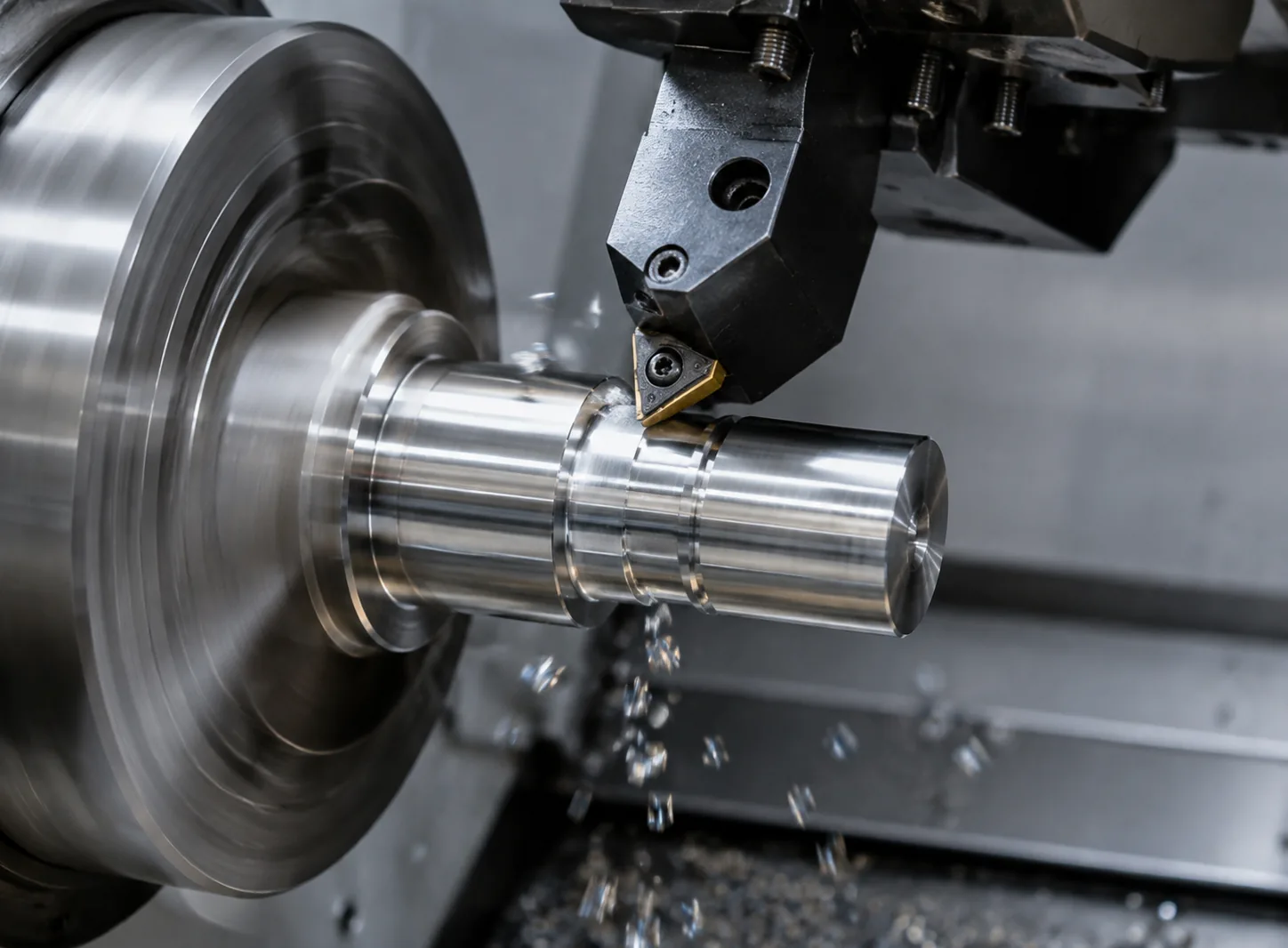
The finish is geometry, not polish
Every rotary cutter leaves a repeating shape on the surface it produces, and that shape is determined by geometry you can calculate before you cut anything. A flat end mill sweeping across a face does not leave a perfectly flat surface; it leaves a series of grooves whose depth is set by the feed per revolution and the corner of the insert. A ball nose cutter finishing a 3D surface leaves a scalloped pattern, and the height of each scallop — called the cusp height — is set almost entirely by the stepover and the radius of the ball. Shrink the stepover and the cusps flatten out; open it up and they turn into a visible washboard.
The useful thing about cusp height is that it is a solved calculation, not a guess. For a ball nose cutter, the cusp height rises roughly with the square of the stepover and falls as the cutter radius grows. That single relationship explains most of the frustration people have with finish: a small stepover on a small ball gives a smooth surface, while the same stepover on a flat area cut with a square shoulder tool leaves tool marks that no amount of spindle speed will erase. The finish is written into the geometry of the cut, and the only way to change it is to change the geometry — a tighter stepover, a larger radius, or a different strategy that keeps the cutter climbing the right way across the part.
This is also why the same cutter can produce two different finishes on two different slopes. A ball nose that cuts near its tip, where the effective radius is small, leaves a coarser finish than the same ball cutting on its side, where the full radius is engaged. Programmers who understand this tilt the part or the cutter so the flank does the finishing work, and they leave the tip for the corners where nothing else fits. Finish is not a single knob; it is a set of geometric choices that have to be made together.
Stepover and cusp height: the two numbers that decide the texture
Stepover is the distance the tool advances sideways between passes, and it is the single most powerful finish control in milling. Halving the stepover on a ball nose finish pass cuts the cusp height to roughly a quarter of what it was, which is why going from a 0.5 mm stepover to a 0.25 mm stepover produces such a visible improvement even though it doubles the number of passes and the time. The trade is always the same: a finer finish costs cycle time, and the cost is not linear. The passes multiply as the stepover shrinks, so chasing the last few microns of Ra can add more machine time than everything that came before it.
The cusp height you can tolerate is the number that should be driving the stepover, and it comes from the print. A surface called out at Ra 0.8 has very different stepover requirements from one called out at Ra 3.2, and treating them the same either wastes time on the rough surface or undershoots the fine one. A useful working rule is to set the stepover so the calculated cusp height sits comfortably below the target roughness, leaving margin for the wobble that real cutting always adds — tool deflection, machine vibration, and the fact that material never cuts exactly like the calculator says it will.
Cutter corner radius plays the same role on flat faces that the ball radius plays on 3D surfaces. A face mill or an end mill with a larger corner radius leaves a broader, shallower scallop for the same feed, so a part that shows visible tool marks with a sharp-corner tool will clean up noticeably with a bull-nose cutter of the same diameter. The radius is free finish, in the sense that it costs nothing in cycle time — you change the tool, not the feed rate — and it is usually the first thing to try before reaching for a finer stepover.
| Finish lever | What it changes | Typical effect on Ra |
|---|---|---|
| Stepover (ball nose) | Cusp height between passes | Halving stepover cuts cusp ~4x |
| Cutter radius / corner radius | Scallop depth on faces and slopes | Larger radius = shallower scallop |
| Feed per tooth | Groove spacing and surface tearing | Lower feed = finer, up to a point |
| Spindle speed / surface speed | Built-up edge and smear | Too low drags and tears material |
| Climb vs conventional milling | Cut direction and rubbing | Climb gives cleaner cut on most alloys |
| Tool condition | Edge wear and chipping | Worn edge ruins any parameter set |
Speed and feed matter after the toolpath does
Once the stepover and cutter radius are set, speed and feed decide whether the theoretical finish actually shows up on the part. The relationship is not "faster spindle, better finish" — it is that each material has a surface speed range where the chip forms cleanly and the edge stays sharp, and leaving that range in either direction degrades the surface. Run aluminum 6061-T6 too slow and the material smears and sticks to the cutting edge, dragging a torn finish across the part. Run it too fast and the tool heats up, the edge dulls, and the finish collapses over the course of a long pass.
Feed per tooth is the other half, and it interacts with the cusp geometry directly. A higher feed leaves wider, deeper grooves and more visible cutter marks, but it also changes how the chip forms — too low a feed per tooth makes the tool rub instead of cut, which polishes in the short term and wrecks the edge in the long term. There is a sweet spot for every tool and material, and finding it is the difference between a finish that looks good on the first part and one that holds through the whole run. Finish programs that ignore feed per tooth and just slow the spindle down usually make the surface worse, not better.
The condition of the cutter is the wildcard that overrides all of this. A finish pass run with a worn or chipped edge will show a bright, smeared, or torn surface no matter how carefully the stepover was chosen, because the damage on the edge is being transferred to the part on every revolution. This is why good shops dedicate finish cutters — a sharp tool used only for light finishing cuts — and why a finish that degrades part-way through a batch is almost always a tool wear signal rather than a programming problem. The finish is only as good as the edge that is cutting it.
Climb milling, entry, and the details that show up at the edges
The direction of the cut matters more than most people admit, especially on the surfaces people actually look at. Climb milling, where the cutter feeds in the same direction as its rotation, slices the chip from thick to thin and tends to leave a cleaner, less torn surface on aluminum and most steels. Conventional milling cuts from thin to thick and rubs the material at the start of each cut, which is harder on the edge and rougher on the surface. For finish passes on a free-cutting alloy like 6061-T6, climb milling is the default, and the only common reason to switch is to avoid chatter on a thin wall or a tall feature where the climb cut pulls the part.
Entry and exit leave their own signature. Plunging a cutter straight into a surface and then feeding leaves a dwell mark where the tool hesitated, and exiting a cut by dragging the edge off the part can leave a burr or a smeared line right where the eye lands. The clean way in is an arc or a ramp entry that feeds the tool into the cut gradually, and the clean way out is a tangent lead-out that lets the tool leave the material without a hard stop. These are small moves in the code, but they are exactly the kind of detail that separates a surface that looks machined from one that looks finished.
The same logic applies to how the passes are ordered and where they start. A raster finish pass that alternates direction across a face can leave a visible direction change where the tool reverses, so the better choice on a surface that will be seen is often a spiral or a one-way pass that keeps the cutter always moving the same way. The toolpath is a text file, and the choices buried in it — the direction, the entry, the lead-out, the stepover — are what actually end up printed on the part.
Toolpath strategy for the finish you are trying to hit
There is no single best toolpath for finish; there is a best toolpath for the surface you are cutting and the number you have to hit. A flat, cosmetic face wants a strategy that keeps a constant, light engagement — a spiral or a clean one-way raster with a small stepover and a fresh finish cutter. A curved 3D surface wants a ball nose running a tight stepover with the cutter tilted so the flank does the work, and the scallops left by the pass are then the texture, so the stepover is set to keep them below the target. A pocket floor that no one will ever see wants the opposite: the largest stepover and feed that hold tolerance, because finish there is time being thrown away.
The practical skill is matching the effort to the requirement. The print drives everything: an Ra 3.2 surface and an Ra 0.8 surface are not two settings on the same program, they are two different programs with different tools, different stepovers, and different amounts of machine time. Treating every surface as if it were a mirror is how a shop burns its margin, and treating a mirror surface as if it were a pocket floor is how it ships parts that get rejected. The finishing pass is where a machinist earns their pay, because it is the one place where the difference between a considered toolpath and a default one is visible to anyone who picks the part up.
- Set the stepover from the cusp height — calculate it, do not guess, and leave margin under the target Ra.
- Use the largest practical corner radius — it flattens the scallops for free without slowing the feed.
- Keep the cutter on its flank, not its tip — the ball nose tip is the coarsest part of the tool.
- Stay in the material's surface speed window — too slow tears and smears, too fast burns the edge.
- Set feed per tooth to cut, not rub — rubbing polishes briefly then wrecks the tool.
- Dedicate a sharp finish cutter — never finish with the same tool that roughed the part.
- Climb mill finish passes on free-cutting alloys — and ramp in, do not plunge.
- Match the effort to the print — a mirror finish on a hidden pocket is just wasted machine time.
"Surface finish is not a setting you dial in at the machine; it is a decision you make in the toolpath. The stepover, the cutter radius, and the cut direction fix the texture before the tool ever touches metal, and speed and feed only decide whether that texture comes out clean. Get the geometry right and the finish takes care of itself; get it wrong and no amount of spindle speed will polish a washboard flat."
The finish on a machined part is the last thing anyone checks and the first thing anyone judges, and it is almost entirely a product of decisions made before the spindle spins. Set the stepover from the cusp height, keep the cutter on its flank, stay in the material's speed window, and reserve a sharp tool for the finish pass, and the surface comes out right without a heroic effort. Skip the geometry and chase the speed instead, and you are polishing a pattern that was fixed the moment the toolpath was posted.
If you are chasing a specific finish on a machined part and the current results are not meeting the print, send the drawing over and we will review the toolpath that is producing it — stepover, cutter choice, and the parameters behind the finish. See how we approach CNC milling for controlled finishes and surface finishing after machining, or get a quote on your part.